Yuma Area Office
Facilities
The Water Quality Improvement Center
Research Facilities and Test Equipment - Pilot Scale Systems
Demonstration Scale System (Pilot System No. 1 (PS1))

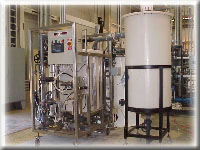
Fluid Reverse Osmosis System
Demonstration Scale System (Pilot System No. 1 (PS1)) is a 600 gallon per minute pilot plant, located within the Yuma Desalting Plant, that is a 1/100th model of the main plant with similar types of equipment and process flows. The pretreatment equipment includes a grit sedimentation basin, intake pumping, solids contact reactor/clarifier, dual media gravity filters, clearwell, and reverse osmosis units. This equipment is similar in type and design to that furnished for the large plant, so that test results can be readily up-scaled and applied to the operation of the main plant.

Solids and sludge handling for PS1are processed in the equipment furnished for the main desalting plant. Reverse osmosis takes place through Hydranautics and Fluid Systems each containing 6 pressure vessels. The capacity for the Hydranautics equipment shown is 64 gallons per minute and the capacity for the Fluid Systems unit is 110 gallons per minute. PS1 models the main plant for optimization studies, performance verification, personnel training, and developmental testing of new systems, and it also serves as the potable water source for the Yuma Desalting Plant facility.
Pilot Systems 2 and 3

The purpose of Pilot Systems 2 and 3 is to evaluate the performance of spiral-wound, nanofiltration reverse osmosis membrane elements. Following the pretreatment process, 12 to 24 gallons of water per minute are supplied to two membrane evaluation research units. Each research unit is arranged with its own feed tank and 21 spiral-wound, 2.5 X 40-inch nanofiltration reverse osmosis elements. The membrane units are designed to operate at recoveries of up to 85 percent. Individual membrane permeate flows and conductivities are monitored on the membrane units' two lead elements, where degradation and biological fouling may occur first, and on the tail element, where scaling and inorganic fouling may be most severe. The permeate characteristics of the other eighteen elements are monitored in groups of three.
Pilot Systems 2 and 3 are configured to supply a wide range of feedwatersto the membrane units. Two membrane units can also be operated in series, for example, with nanofiltration softening followed by reverse osmosis desalting or with spiral-wound ultra filtration followed by nanofiltration or reverse osmosis.
Pilot Scale System Pretreatment Equipment

The Grit Settler removes sand and larger grit to prevent abrasion of the pumps used in the softening process, reduces the fraction of sand in the sludge for sludge recalcining studies, and provides for the evaluation of improved grit settler designs and operations.

The Series Continuous Stirred Tank Reactor (SCSTR) rapidly mixes slaked lime, recycled sludge, and coagulants, (e.g., ferric sulfate) with the process water to precipitate and flocculate calcium carbonate solids. These functions can also be performed in the Solids Contact Reactor/Clarifier described below. The SCSTR, however, enables more detailed evaluations of softening and flocculate formation.

The Solids-Contact Reactor/Clarifier (SCR) settles and removes flocculated calcium carbonate solids produced during precipitation by partial lime-softening and coagulation. The SCR can operate either as a single unit carrying out rapid mix, precipitation, flocculation, and clarification processes, or as a clarifier operating on the SCSTR effluent.
 The Dual Media Gravity Filters consist of 6 individual filter columns, each 30 inches in diameter, which provide depth filtration of clarifier effluent from each filter bank. The product is discharged into two filter effluent tanks which pump into the backwash tankand the membrane unit feed tanks. The Air Scour Blower System supplies air to the gravity filter cells for scouring the filter media during backwash. The Backwash Waste Sump System receives and disposes of waste streams from the gravity filters. The Sample System functions to sample the four gravity filter cells one at a time for turbidity, pH and Silt Density Index. Sulfuric Acid is added to convert carbonate into soluble bicarbonate salt and prevent caking of the gravity filter media. TheBackwash Makeup System functions to transfer treated water from the clearwell to the weir box for use during the gravity filter backwash cycle.

Chemical Feed Systems inject chemicals at controllable rates into the process streams. Chemicals include sodium hypochlorite, lime, sulfuric acid, polymer, ferric sulfate, SHMP, and ammonium hydroxide. Many chemical feed systems are stationary with containment provisions to catch spills while the remaining systems are portable to suit research requirements.
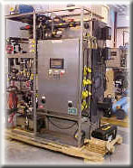
Pretreatment Membrane Units - The Memcor Microfiltration Unit and theZenon Ultrafiltration Unit are self-contained membrane units that serve as a pretreatment tool in a variety of water treatment studies.
-
 Microfiltration Unit
The Microfiltration Unit consists of three individual modules operating at a flow rate of 18 to 20 gallons per minute. The modules each contain 15 square meters of 0.2 micron pore size polypropylene hollow fiber membranes. The feed water flows from outside the hollow fibers into the center and exits as filtrate. Accumulated solids on the outside of the hollow fibers are removed from the system periodically, using feed water and a patented gas backwash. Compressed air at 100 psi is introduced into the filtrate side and released through the walls of the hollow fibers.
Microfiltration Unit
The Microfiltration Unit consists of three individual modules operating at a flow rate of 18 to 20 gallons per minute. The modules each contain 15 square meters of 0.2 micron pore size polypropylene hollow fiber membranes. The feed water flows from outside the hollow fibers into the center and exits as filtrate. Accumulated solids on the outside of the hollow fibers are removed from the system periodically, using feed water and a patented gas backwash. Compressed air at 100 psi is introduced into the filtrate side and released through the walls of the hollow fibers.
-
 Ultrafiltration Unit
The Ultrafiltration Unitconsists of one 42.7 square meter proprietary chlorine-tolerant hollow fiber membrane with a 0.1 micron nominal pore size. The module removes relatively large particles such as microbes, bacteria, and macromolecules with molecular weights greater than 100,000 Daltons. A single module operates at a flow rate of 18 to 20 gallons per minute. A vacuum inside the fibers creates the trans-membrane pressure differential for filtration instead of the conventional positive pressure filtration method. The feed water flows from the outside of the hollow fibers into the center and exits as filtrate. Accumulated solids on the outside of the hollow fibers are scoured from the membrane fibers periodically using a patented aeration method while mixing and maintaining a high flux.
Ultrafiltration Unit
The Ultrafiltration Unitconsists of one 42.7 square meter proprietary chlorine-tolerant hollow fiber membrane with a 0.1 micron nominal pore size. The module removes relatively large particles such as microbes, bacteria, and macromolecules with molecular weights greater than 100,000 Daltons. A single module operates at a flow rate of 18 to 20 gallons per minute. A vacuum inside the fibers creates the trans-membrane pressure differential for filtration instead of the conventional positive pressure filtration method. The feed water flows from the outside of the hollow fibers into the center and exits as filtrate. Accumulated solids on the outside of the hollow fibers are scoured from the membrane fibers periodically using a patented aeration method while mixing and maintaining a high flux.
 Microfiltration Unit
The Microfiltration Unit consists of three individual modules operating at a flow rate of 18 to 20 gallons per minute. The modules each contain 15 square meters of 0.2 micron pore size polypropylene hollow fiber membranes. The feed water flows from outside the hollow fibers into the center and exits as filtrate. Accumulated solids on the outside of the hollow fibers are removed from the system periodically, using feed water and a patented gas backwash. Compressed air at 100 psi is introduced into the filtrate side and released through the walls of the hollow fibers.
Microfiltration Unit
The Microfiltration Unit consists of three individual modules operating at a flow rate of 18 to 20 gallons per minute. The modules each contain 15 square meters of 0.2 micron pore size polypropylene hollow fiber membranes. The feed water flows from outside the hollow fibers into the center and exits as filtrate. Accumulated solids on the outside of the hollow fibers are removed from the system periodically, using feed water and a patented gas backwash. Compressed air at 100 psi is introduced into the filtrate side and released through the walls of the hollow fibers. Ultrafiltration Unit
The Ultrafiltration Unitconsists of one 42.7 square meter proprietary chlorine-tolerant hollow fiber membrane with a 0.1 micron nominal pore size. The module removes relatively large particles such as microbes, bacteria, and macromolecules with molecular weights greater than 100,000 Daltons. A single module operates at a flow rate of 18 to 20 gallons per minute. A vacuum inside the fibers creates the trans-membrane pressure differential for filtration instead of the conventional positive pressure filtration method. The feed water flows from the outside of the hollow fibers into the center and exits as filtrate. Accumulated solids on the outside of the hollow fibers are scoured from the membrane fibers periodically using a patented aeration method while mixing and maintaining a high flux.
Ultrafiltration Unit
The Ultrafiltration Unitconsists of one 42.7 square meter proprietary chlorine-tolerant hollow fiber membrane with a 0.1 micron nominal pore size. The module removes relatively large particles such as microbes, bacteria, and macromolecules with molecular weights greater than 100,000 Daltons. A single module operates at a flow rate of 18 to 20 gallons per minute. A vacuum inside the fibers creates the trans-membrane pressure differential for filtration instead of the conventional positive pressure filtration method. The feed water flows from the outside of the hollow fibers into the center and exits as filtrate. Accumulated solids on the outside of the hollow fibers are scoured from the membrane fibers periodically using a patented aeration method while mixing and maintaining a high flux.For more information about the Research Facilities at the Water Quality Improvement Center, contact Angela Adams, Desalting Group, through email or by phone at 928-343-8114.
Back to Research Capabilities Main Page
For Telecommunications Relay Services (TRS) Dial: 711
Webmaster: sha-YAO-WebComments@usbr.gov
