

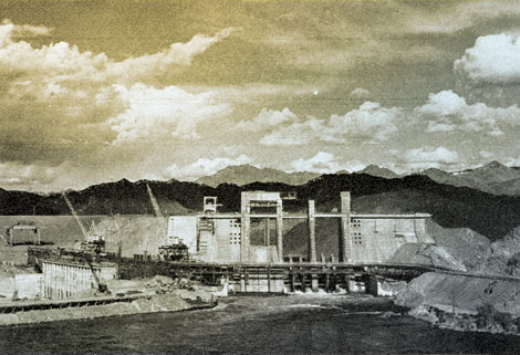
 The river is rising – but no cause for alarm. A lake 67 miles long is being created behind Davis Dam, shown with the stop logs in place, raising the water at the dam to a depth of 70 feet. The Arizona end of the dam is at the left.
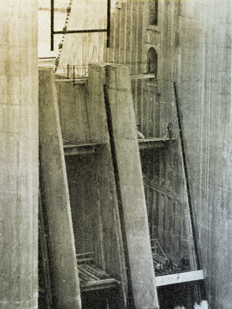 Bird's eye view of workmen lowering one of the 240 concrete stop logs (each 13 ½ feet long and weighing 6 tons) into one of the slots in the spillway of the dam.
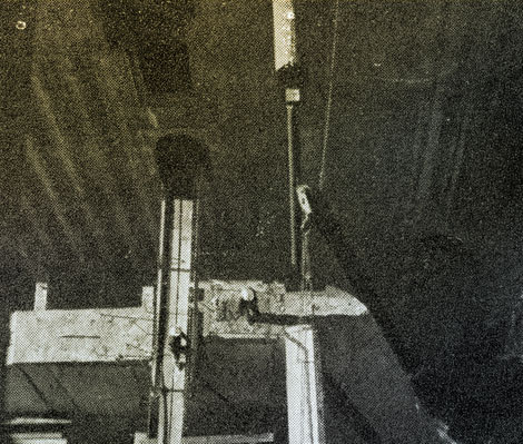 Stop log No. 202 going into place.
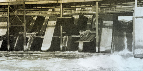 You can see the water flowing through the radial gate outlet at the right of the picture. The other outlet on the opposite side of the spillway is not in the photo. This operation backed up the river 30 miles.
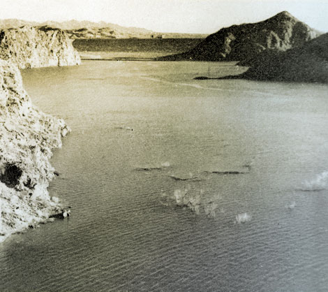 Each room with a view like this. The National Park Service photo above was taken from a spot close to the proposed lodge site at Katherine Wash as the new lake began to form behind Davis Dam.
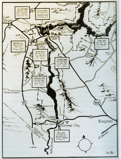 Map submitted through the courtesy of the National Park Service.
 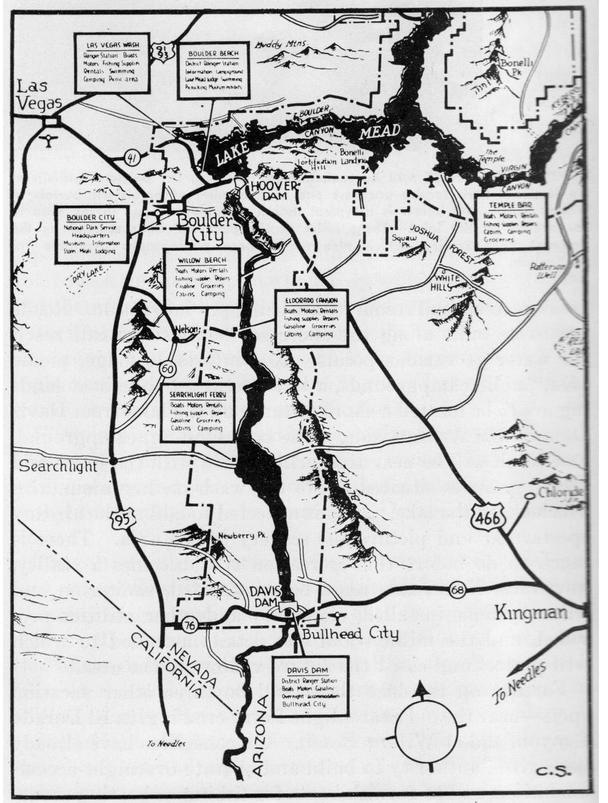 View large image
 Proud of their water purifier are Mr. and Mrs. Gerald L. Didier as they point to part of the water system that they have installed on their homestead on the Yuma Mesa Division, Gila project. The system includes the water softener to Mr. Didier's right, the germicidal lamp purifier in the middle, and the automatic water heater to Mrs. Didier's left. Photo by M. N. Langley of the bureau's Region 3.
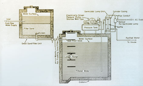 The "Violet Ray" treatment devised at Yuma Mesa. The diagram shows the pipe entering about three-quarters of the way up the cylinder casing. In Didier's purifier, water rises around lamp, is circulated by several baffles and leaves through outlet pipe seen near top on front of unit. In diagram, outlet pipe is shown near bottom of right-hand side of lamp unit. The illustration on this page is based upon shop drawings for the construction of purifying unit made at the district manager's office of the Lower Colorado River District, Yuma, Ariz. District Manager M. J. Miller states they have not yet attempted to make refinements in design that would be desirable if such units were to be manufactured in quantities. Illustration prepared by Bureau's Graphics Section in Washington, D.C., based on Region 3 drawing.
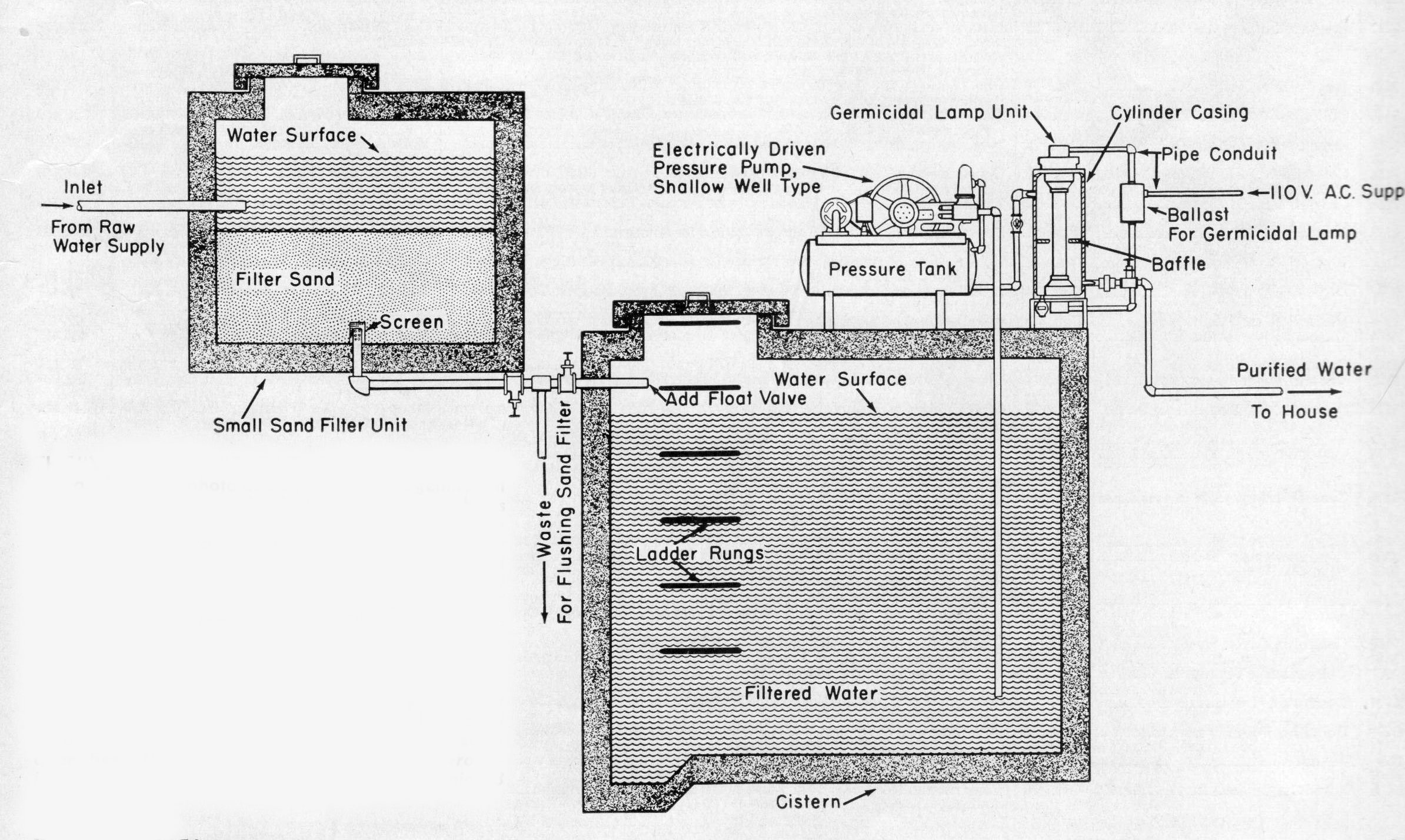 View large image
 Discussing water rights, a western pastime.
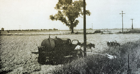 Diesel Oil Does It – Johnson Grass getting an application of diesel oil by a member of the Salt River Valley Water Users Association. Photo by C.W. Bowser of Region 3, Bureau of Reclamation.
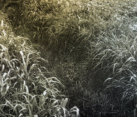 Half and Half – a stand of Johnson Grass treated with an emulsion of 50 percent aromatic oil and 50 percent water. Each of the seven applications was made at a rate of 160 gallons per acre, using a total of 560 gallons of aromatic oil per acre. Note heavy growth of grass which remains.
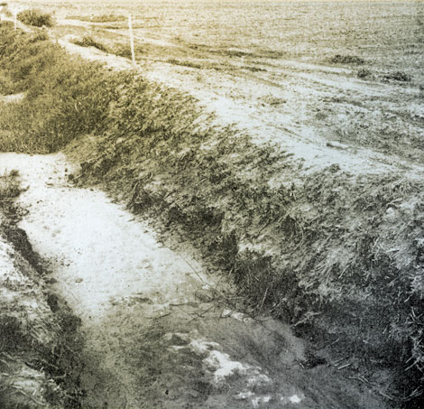 Full Strength – What was left of Johnson Grass after being treated with undiluted aromatic oil. Each of the first two applications was made at 160 gallons per acre. Five following applications made at continuously decreasing volumes. Total volume of all used, 585 gallons per acre. Note stream condition.
 Arizona's Water Master, Mark Wilmer
Photo courtesy of Snell & Wilmer