- Reclamation
- Missouri Basin and Arkansas-Rio Grande-Texas Gulf
- Programs & Activities
- CMR&I – Project Description
Crow Tribe Municipal, Rural, and Industrial Water System – Project Description
The proposed MR&I Project would be a region-wide water distribution network for the Reservation. The Settlement Act divides the project area into three subsystems, prioritized according to the order in which each area would become a part of the MR&I Project. The Settlement Act specifies the priority of the service areas as 1) Bighorn Valley Subsystem, 2) Little Bighorn Subsystem and 3) Pryor Extension, shown below in Figure 1.
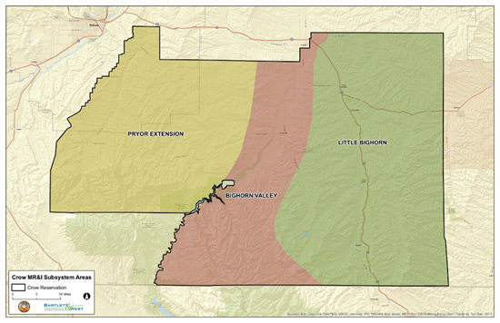
Figure 1: Overview of MR&I Project Subsystems
Service Area
The proposed system would be built with the capacity to produce a maximum of 6.7 million gallons of water per day, which would be enough water to serve all three service areas and the city of Hardin. The city of Hardin is located outside of the Reservation and currently has not requested to connect to the MR&I system. However, the EA and the Master Plan have taken the possibility of Hardin connecting to the system into consideration. As currently planned, the system would be operated to produce only 4.5 million gallons of water per day to serve the three service areas shown above.
Because the project is expected to take 15 to 20 years to complete, community upgrades such as new pipes and additional wells would be implemented as needed in communities that would not be reached by the regional pipe network for several years. These upgrades would ensure adequate water supply and quality to communities such as Pryor and Wyola, which would not be reached by the regional system for many years.
Facilities Overview
The MR&I Project will consist of construction of the following facilities:
- Raw Water Intake
- Water Treatment Plant (WTP)
- Distribution System
- Pump Stations
- Storage Tanks
- Pipeline Accessory Structures and Service Connections
- SCADA and Electrical
Raw Water Intake
The proposed raw water intake would be constructed on the bank of the Bighorn River. The exact location would depend on land purchase negotiations, geotechnical investigations, a hydrogeology evaluation, and other evaluations to verify viable intake structure options. Figure 2.2 of the EA shows the intake location alternatives under consideration.
Two intake types are under consideration: 1) riverbank filtration, which would draw groundwater under the influence of surface water from beneath the riverbed, or 2) surface intake, which would draw surface water directly from the river. Figure 2.4 of the EA has a display showing each of the proposed methods. The preferred intake type is riverbank filtration, drawing groundwater under the influence of surface water from alluvial sand and gravel layers under the Bighorn River. Riverbank filtration is preferred because it provides natural filtration of sediment, debris, and contaminants prior to intake, resulting in reduced chemical use during pretreatment and reduced need for disinfection. In turn, this generates less sludge and makes it easier to meet SDWA rules. Raw water from riverbank filtration is more consistent in quality and temperature and typically has minimal color, odor, turbidity, and algal issues, resulting in less facility maintenance. The use of riverbank filtration is not intrusive to the river bottom or subject to damage and blockage by ice and debris in the river. It is not susceptible to invasive plant infestation and has no impact on fisheries or aquatic life.
Several alternate intake locations and intake types remain under consideration. Riverbank filtration is the preferred type, but a surface water intake is still under consideration. A surface water intake would consist of a screened inlet at the end of a pipe(s) within three feet of the river bottom. If a surface intake would be selected, mitigation measures would be implemented to minimize impacts to fish, aquatic life, and recreational use of the river (see Section 2.4.5 of the EA, Environmental Commitments).
Water Treatment Plant (WTP)
The proposed WTP would be near the town of St. Xavier, on land owned by the Tribe. The final location of the WTP would depend on land negotiations, geotechnical investigations, and other evaluations. The maximum capability of WTP would produce 6.7 mgd with service to Hardin. The footprint associated with the WTP site would be in the range of approximately 40 to 60 acres for both short-term construction disturbance and the area occupied by permanent WTP facilities.
The preferred water treatment process (also known as a "treatment train") includes the following main steps, which are illustrated in a flow schematic in Figure 2.7 of the EA:
- Pretreatment Oxidation, Coagulation, Sedimentation: Breaks down contaminants (such as iron, manganese or taste and odor causing compounds) into a more removable state and reduces the amount of suspended solids from the water before sending it through a filter (step 2).
- Micro/Ultra Filtration: Filters water to further remove suspended solids, organics, pathogens, and other particulates.
- Nanofiltration/Reverse Osmosis Softening: Softens the water, removes broken down contaminants (see step 1), and improves taste and odor.
- Chlorine Disinfection: Disinfects the filtered water by killing waterborne pathogens.
The preferred method for disposing of the wastewater stream is to discharge into the Bighorn River. The proposed discharge outlet would consist of a pipeline exiting the riverbank into the deepest portion of the river bottom, capped with a perforated pipe. The perforated pipe would help to speed up the dilution of the waste stream once it is mixed with the river water. All discharges into the Bighorn River would require approval and permitting from EPA. No additional acreage for evaporation ponds would be needed for this method. This option is preferred because it is the simplest and least expensive disposal option.
Multiple options exist for the disposal of the wastewater stream other than discharging to the river. Other options include, in order of preference:
- Further treatment of a portion of the liquid waste stream. The treated portion of the liquid wastes would be discharged into the Bighorn River and the remaining, untreated portion would be sent to evaporation ponds or lagoons. As with the preferred disposal method, this disposal method would require approval by the EPA. Up to an additional 60 acres of evaporation ponds would be needed for the untreated portion of the liquid waste stream;
- Sending all liquid wastes to evaporation ponds or lagoons. Up to an additional 190 acres would be needed for evaporation ponds; or
- Deep well injection of all liquid wastes. The possibility of deep well injection would depend on geotechnical investigations and other further evaluations.
These options are described in more detail in the Master Plan (p. 365-368) and would be further evaluated during the design phase, if the preferred disposal method is not approved.
Distribution System
Approximately 750 miles of pipeline would be used to distribute water to the three service areas of the Reservation (Figure 2.1 of the EA). The proposed system would include transmission main pipelines and distribution pipelines. The pipelines would be primarily polyvinyl chloride and ductile iron pipe and would vary in diameter between 1.5 inches and 24 inches, with the majority being between two and eight inches in diameter. The pipelines would be buried to a minimum depth of six feet or below the known frost depth, whichever is deeper. The main transmission pipelines would be generally aligned to roads or other existing features such as fence lines or section lines to reduce the cost for acquiring easement access and for efficient construction and maintenance. Distribution pipelines are smaller diameter pipes (typically less than six-inch diameter) that convey flow from regional storage tanks to points of use within each service area (i.e., rural service connections or community tanks).
Pipeline alignments may be adjusted during the design phase, depending on easement negotiations and other site-specific engineering and environmental considerations. Main transmission pipeline easements would be 50 feet wide for permanent easements and 100 feet wide for temporary construction easements. Distribution pipeline easements would be 30 feet wide for permanent easements and 50 feet wide for temporary construction easements.
Approximately 5,300 acres would be disturbed for pipeline construction if all distribution and service lines were installed; this entire area would be reclaimed in the long-term, with a minor permanent acreage needed for aboveground pipeline markers and pipeline accessory structures (See Pipeline Accessory Structures and Service Connections and Table 2.7 of the EA). Pipelines would cross roads, railroads, utility lines, rivers and streams, irrigation canals and other facilities. (See Appendix C of the EA for descriptions of typical construction and trenching steps.)
Storage Tanks
Seven regional storage tanks (Table 2.3 of the EA) and three new community tanks (Table 2.4 of the EA) would be used to store water and provide pressure to the system when pump stations are not pumping. The regional tanks would be larger than community tanks, would provide water for emergency water use, and equalize storage during times of peak water use. New community tanks in Crow Agency, Pryor, and Lodge Grass would provide back-up storage to meet the average-day water demand plus additional capacity to meet fire flow demands within those respective communities. Community storage requirements for Wyola, St. Xavier, and Fort Smith would be provided by the regional tanks located in or near those communities; a separate tank dedicated to community storage would not be built in these communities.
Pump Stations
Pump stations would be needed to deliver water to some areas. The Proposed Action Alternative includes 13 pump stations to serve the main transmission pipeline and 34 to serve the distribution pipelines (Figure 2.1 of the EA). Final site locations of the pump stations would be determined during the design phase based on engineering, realty, environmental, and other considerations. Approximately 20 to 25 of the distribution pump stations would be located near the ends of pipeline branches that serve a very small number of users. The feasibility of serving these residences would be further assessed during final design, but have been included as part of the proposed action. Pumps would be located in aboveground buildings or underground prefabricated steel vaults. Either option would occupy an area of approximately 50 feet by 50 feet (less than 0.10 acre).
Pipeline Accessory Structures and Service Connections
Several types of pipeline accessory structures would be installed along the length of the pipeline. These structures include pressure reducing valves, flow control valves, air release valves, clean-out assemblies, and flush hydrants (further detail is provided in the Master Plan, Sections 6.11, p. 227-239). These structures serve various functions in operating and maintaining the pipeline system. These structures would be installed in buried concrete vaults or manholes for operator accessibility, with a small area of aboveground features, estimated to be less than 0.5 acres total for all structures combined. The structures would be contained within the pipeline or facility easements, typically on section lines or fence lines so maintenance activities would not interfere with land uses.
Preliminary system design includes water service connections to all 1,415 existing rural residences. The maximum amount of water a user would receive if all users were to take water at the same time over an entire day is 720 gallons per day (gpd). For the communities, the usage rate would be measured in gallons per capita per day (gpcd), as opposed to per service unit for rural users. The peak day usage rate for communities is designed at 450 gpcd. This rate accounts for MR&I system water demands by all water use sectors within the community including residential, commercial, and industrial.
Water meters would be provided for all users of the system to track water usage, prepare water bills, promote water conservation, and facilitate detection of leaks. Service connections for the proposed project would include master meters for communities and industrial connections and individual meter boxes for each rural user and livestock connections (Table 2.5 of the EA).
For rural users, a service line would be extended from the distribution pipeline into the user’s yard near the user's structure. Up to 100 feet length of pipe would extend from the meter box to make the service connection into their structure and existing plumbing. For urban users, service meters would be installed as either an interior meter located within the user's basement or as part of a community master meter. A remote meter readout device would be installed to allow the meter to be read without entering the user's structure.
The proposed project would provide a supplemental supply of water to serve approximately 48,000 cattle on the Reservation at 16.5 gpd per animal, for a total of approximately 792,000 gallons. For planning and cost estimating purposes, it was assumed that 480 livestock connections would be provided, or one connection for every 100 head of cattle served. Rural users with large livestock or feedlot operations would have an opportunity to sign up for multiple service units during a sign-up campaign in advance of final design, although the additional service units are not guaranteed. The quantity of water and the water connections is expected to be used by other livestock and wildlife. For livestock users, a meter box assembly would be installed along with a yard hydrant on the downstream side of the meter box. Livestock users would be responsible for providing a watering tank, cross connection control devices, and flow limiting valves.
Supervisory Control and Data Acquisition (SCADA) and Electrical System
A SCADA system would be used for monitoring and operation of the proposed project. Sensors throughout the system would convey information to the central control facility at the WTP, where trained personnel would operate the SCADA. Extensions to the electrical system would be needed to operate the SCADA and for some of the equipment at the intake and WTP. Both single-phase 120-volt and three-phase 240 or 480-volt power would be required; most are anticipated to be overhead lines, however, some may be underground depending on site conditions (Table 2.6 of the EA). Standard overhead powerline height is a minimum clearance of 18 feet. Powerline routes would be finalized during the design phase based on engineering, realty, environmental, and other considerations.
Operations & Maintenance
As construction of MR&I system facilities are completed, the United States would convey title of those facilities to the Tribe for OM&R as defined in the Settlement Act. Routine OM&R of MR&I system facilities, and replacements, additions, and extraordinary maintenance are critical to providing a reliable high-quality water supply over the 50-year design life of the proposed project. OM&R would require up to 28 permanent, full time staff with oversight by a five-member Board of Directors.
The Tribe intends to charge a monthly water bill to help pay for the annual costs for OM&R of the MR&I system, as authorized by the Settlement Act (Section 406(i)). Funds from the MR&I system OM&R Account in the Crow Settlement Fund would be used to assist the Tribe in paying MR&I system OM&R costs. Final decisions regarding the rate schedule, along with the use of the OM&R fund, would be developed in conjunction with the MR&I system Operation, Maintenance, and Replacement Plan, which would be completed when the WTP is operational.
Facilities needed for OM&R include an administration building, permanent storage facilities, and maintenance shop, along with equipment such as operator pickup trucks, service vehicles, and excavators. The proposed location for the administration building is in Crow Agency (Figure 2.8 of the EA). A permanent facility near St. Xavier would be used for construction, operations, and permanent storage for tools and equipment. The proposed locations for these facilities would be finalized during the design phase based on engineering, realty, environmental, and other considerations.
Community Upgrades
Community upgrades would be implemented as needed in communities that would not be reached by the regional pipe network for several years. Pryor, Wyola, and Lodge Grass upgrades would include replacing existing pipelines and associated accessory structures, installing new service lines to users, and rehabilitating or replacing their water source. Rehabilitation or replacement of the water source may include replacing or upgrading parts of a well such as a pump, valves, or equipment; drilling a new well(s); or installing a chemical feed system in the interim where there is inadequate equipment.
Because the draft EA does not evaluate drilling new wells, the evaluation of drilling new wells would be evaluated as a separate NEPA action.
Once the MR&I system reaches the communities, the existing source would be physically disconnected from the system but could be used for other purposes and serve as a backup water source in cases of emergency. Crow Agency would also receive upgrades including replacing existing pipelines and associated accessory structures and installing new service lines to users. Community upgrades would occur within the limits of existing community water systems, which are mainly within city limits and previously disturbed areas.
