|
|
CHAPTER 7 - WEIRS
(a) Compound Weirs
Unusual situations may require special weirs. For example, a V-notch weir might easily handle the normal range of discharges at a structure; but occasionally, much larger flows would require a rectangular weir. A compound weir, consisting of a rectangular notch with a V-notch cut into the center of the crest, might be used in this situation. A weir of this type is shown on figure 7-10.
|
|
The compound weir, as described, has a disadvantage. When the discharge begins to exceed the capacity of the V-notch, thin sheets of water will begin to pass over the wide horizontal crests. This overflow causes a discontinuity in the discharge curve (Bergmann, 1963). Therefore, the size and elevation of the V-notch should be selected so that discharge measurements in the transition range will be those of minimum importance.
Determining discharges over compound weirs has not been fully investigated either in the laboratory or in the field. However, an equation has been developed on the basis of limited laboratory tests on a 1-ft-deep, 90-degree V-notch cut into rectangular notches 2, 4, and 6 ft wide to produce horizontal extensions of L=0, L=2, and L=4 ft, respectively (Bergmann, 1963). The weirs were fully contracted, and heads up to 2.8 ft above the notch point were used. The equation is as follows:
![]() (7-8)
(7-8)
where:
Q = discharge in ft3/s
h1 = head above the point of the V-notch in ft
L = combined length of the horizontal portions of the weir in ft
h2 = head above the horizontal crest in ft
When h1 is 1 ft or less, the flow is confined to only the V-notch portion of the weir, and the standard V-notch weir equation (Eq. 7-6) is used.
Further testing is needed to confirm this equation before it is used for weirs beyond the sizes for which it was developed.
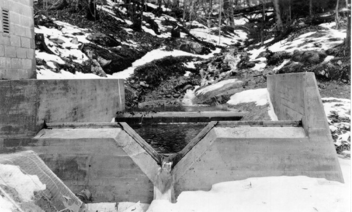
(b) Short Weir Box Turnouts
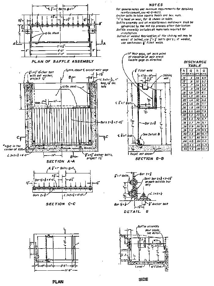
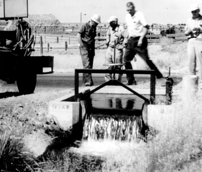
A simple and inexpensive irrigation turnout structure regulates rate of flow and provides a relatively quiet headwater pool in a short approach distance from canal pipe outlets into weir boxes. These measurement structures overcome defects in approach conditions not accepted by standard weir pools by using a combination of baffles and a shelf type gage stilling basin. This concept was first developed on the Yakima Project in Washington using Cipoletti weirs. One of the structures used for discharges up to about 1.5 ft3/s is shown on figure 7-11. This weir box was used to measure flows where the head differences between the canal water surface and the weir pool surface were as much as 4 ft. Discharges were determined by using the standard Cipoletti weir calibration in table A7-5.
|
|
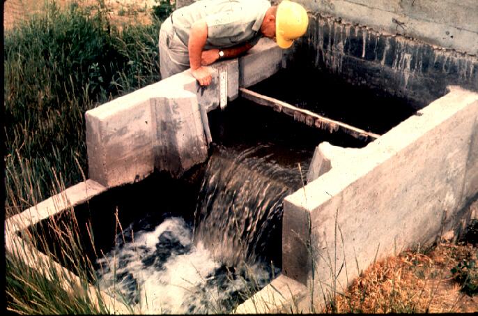
Simmons and Case (1954) and Palde (1972) studied this concept further to improve approach flow velocity distribution, still the water surface at the gages, and increase discharge measuring capacity, accuracy, and head differential between the supply canal head elevation and weir pool. To achieve narrower box widths, suppressed rectangular weirs were installed for full size laboratory tests. These tests developed system arrangements, box and weir dimensions, and stilling baffle arrangements (figures 7-12c and 7-13) and calibrations for discharges up to 12 ft3/s and for canal and weir pool head differences up to 6 ft. Suppressed rectangular weirs 3 and 4 ft long were used rather than Cipoletti weirs to simplify the structure and increase capacity. To meet three different conditions likely to be encountered in the field, the three designs for 5.0-ft3/s maximum measuring capacity shown on figure 7-12 were prepared.
|
|
|
|
|
|
|
|
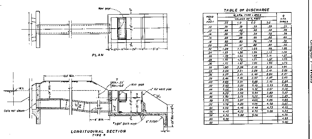
The type 1 turnout weir box (figure 7-12a) is placed immediately adjacent to the supply canal with the turnout inlet recessed into the side of the canal. The type 2 turnout (figure 7-12a) is placed farther from the canal. Maximum discharge for turnout types 1 and 2 is 5.0 ft3/s with a maximum head drop between the canal water surface and the weir pool surface of 3.0 ft. The type 3 (figure 7-12b) turnout is designed for 5.0 ft3/s with a head drop of up to 6.0 ft. Instead of having the square bottom gate at the weir pool headwall, the gate is moved to the canal pipeline inlet.
Discharges through types 1 and 2 weir box turnouts are determined by measuring the weir pool head, h1, on the weir gage provided just above the baffles and wave suppressor, measuring the head drop, Y, using the weir gages both upstream and downstream from the gate, and using the table of discharge on figure 7-12b. Both weir gages should be set at the same elevation. Discharges through type 3 turnouts are determined by the single measurement of weir pool head, h1, and the table of discharge on figure 7-12b, depending on maximum design discharge measurement capacity.
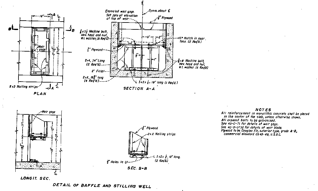
The baffle arrangement and rating table for the 12-ft3/s maximum capacity weir box developed by Palde (1972), shown on figure 7-13, incorporates a suppressed weir. This weir box is installed in gate, pipe, and box configuration similar to the smaller discharge capacity weir box in the type 3 turnout using the dimensions and baffle arrangement shown on figure 7-12b, which also shows the calibration chart.
All four designs are arranged to permit easy construction as in-place structures or as precast units. All use reinforced concrete for the main box and headwalls and use separate, easily replaced, wooden or metal baffle assemblies in the weir pool. A space is left open at the upstream face of the baffle so any accumulations of weeds and debris can be removed. Design and construction details for the 5- and 12-ft3/s weir boxes are given in Aisenbrey et al. (1978).
(c) Broad-Crested Weirs
A broad-crested weir is a raised overflow crest, commonly a flat horizontal block. However, a variety of crest shapes can be used to establish flow control in boundaries that are horizontal in the direction of flow. Broad-crested weirs often have special approach transitions ahead of and up to the crest surface, such as nose treatments like ramps and rounded corners. Crest length in the direction of flow is generally long enough, relative to the measuring head, to make the effect of flow curvature insignificant and short enough to prevent friction from controlling depths. These weirs can be computer calibrated when flow curvature is insignificant.
Broad-crested weirs are about as accurate as sharp thin-plate
weirs and also have some advantages, such as:
No clear-cut classification distinction or hydraulic difference exists between broad-crested weirs and long-throated flumes. Computer calibrations of broad-crested weirs use the principles and theories that are used for long-throated flumes. Thus, broad-crested weirs such as flat crests across trapezoidal and circular flow channels are covered in chapter 8.
(d) Movable Weirs and Adjustable Weirs
Movable weirs are weir assemblies mounted in metal or timber frames that can be moved from one structure to another. The frames fit freely into slots provided in the structures and are not fastened in place. Adjustable weir assemblies are mounted in metal frames permanently fastened to the structures. The weir blades in both the movable and the fixed frames can be raised or lowered to the desired elevations, usually by threaded stems with handwheels.
An adjustable weir used at a fixed frame location is shown on figure 7-14. A sufficiently large pool must be provided upstream from the weir to slow and quiet the flow before it reaches and overflows the weir blade. A fixed head gage is not recommended for flow measurement if the weir is to be moved up or down because the gage zero will not coincide with the weir crest elevation.
|
|
A form of a movable crest broad-crested weir is discussed in Bos (1984) and Bos et al. (1991). This publication also shows how movable weirs can be arranged to provide shutoff and sediment sluicing provided enough channel drop is available.
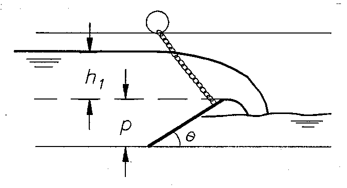
(e) Flow Measurement Using an Overshot Gate
Overshot gates (figure 7-15), or leaf gates as they are sometimes called, are increasingly used for controlling water levels in open channels. This application is used partly because of the ability of the gates to handle flow surges with limited depth changes and the ease with which operators can understand their hydraulic behavior. With an overshot gate, a 6-in drop in the gate height corresponds closely to a 6-in drop in upstream water level. The main purpose of most main canal control gates is to maintain a constant water depth for turnouts located upstream. Thus, the turnouts will deliver water at nearly constant flow rates regardless of the flow rate in the main canal. If the water level in a main canal is constant, then turnout controls can be either weirs or orifice-based gates, such as sluice or radial gates. Generally, weirs are able to control main canal water surfaces more closely than orifice gates because the water level upstream varies with the three-halves power of the head over the weir compared to the one-half power for orifices.
|
|
Although water level control is useful, operators also need to know the flow rate at each gate to better operate systems. Wahlin and Replogle (1994) further developed the Kindsvater and Carter (1959) calibration approach for a sloping leaf gate as a weir by modifying equation 7-1 with a gate angle correction coefficient, Ca, as follows:
![]() (7-9)
(7-9)
where:
Ca = correction factor for angle of the gate
Ce = effective discharge coefficient for a vertical weir from figure 7-5 or equation 7-2
Le = effective crest length
he = effective measurement head
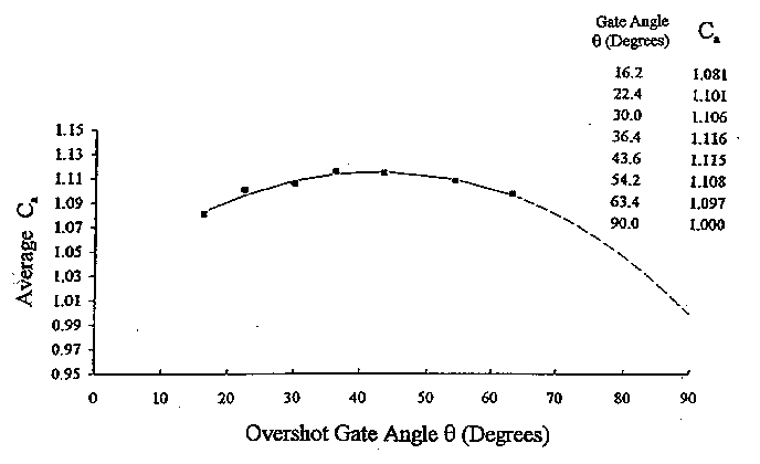
An empirical plot (figure 7-16) for Ca was determined from laboratory tests. For values of h1/p less than 1.0 and for gate angles between 16.2 degrees and 63.4 degrees, the relationship for Ca is:
|
|
The angle, ![]() , is measured in
the direction of the flow between the channel invert and the underside
of the gate leaf in degrees.
, is measured in
the direction of the flow between the channel invert and the underside
of the gate leaf in degrees.
Ca = 1.0333 + 0.003848![]() - 0.000045
- 0.000045![]() 2 (7-10)
2 (7-10)
These equations can determine the flow rate in the field of a properly ventilated free-flow leaf gate to within about 6.4 percent. These equations were tested against hydraulic laboratory modeling and field data. Eventually, with further testing, these authors expect to verify that their derived submergence functions will provide submerged flow calibrations to within about 10 percent. This accuracy estimation for submerged flow rate does not include errors associated with head measurement.
An example computation of free overshot discharge follows.
For a leaf gate that is 6.5 ft wide and 9.75 ft long, sloping at 40 degrees, mounted with the hinge point about 3 in above the invert, and a measurement head, h1, of 3.25 ft, calculate the free flow discharge.
The overfall edge of a leaf gate is in a region of no side contraction; therefore, the effective discharge coefficient can be calculated assuming no side contractions of the weir. Thus, figure 7-5 or equation 7-2 with a C1 of 0.40 and C2 of 3.22 are used to calculate a value for the effective discharge coefficient, Ce, as 3.42 at h1/p of 0.5.
Because no effects caused by side contractions were assumed, a value of -0.003 ft is assigned to Kb (figure 7-4). Kindsvater and Carter (1959) also recommend that a constant value of 0.003 ft be assigned to Kh regardless of the flow rate or gate height. Thus, Le is 6.497 ft, and he is 3.253 ft.
Because h1/p is less than 1.00, and the gate angle is between 16.2 and 63.4 degrees, equation 7-10 can be used to determine that Ca is 1.115. Then, equation 7-9 is used to calculate discharge as below:
![]()
Q = 145.3 ft3/s
(f) Short-Crested Triangular Weirs
The Soil Conservation Service, now the Natural Resources Conservation Service, (Brakensiek et al., 1979) (U.S. Department of Agriculture, 1962) developed a triangular short-crested weir (referred to by some investigaters as a triangular broad-crested weir) in the 1930's. The short-crested triangular design was adopted to provide a precalibrated meter installation that is economical, durable, and accurate over a wide flow range. The weirs are typically constructed entirely of reinforced concrete. The standard dimensions of the weir crest are given on figure 7-17. Triangular weirs with crest slopes of 2 to 1, 3 to 1, and 5 to 1 are standard. A concrete apron is recommended downstream from the weir for a distance of two measuring heads to prevent erosion. Water stage is measured relative to the weir Vnotch at a location 10 ft upstream from the centerline of the crest profile. The U.S. Natural Resources Conservation Service recommends the channel upstream from the weir be nearly straight and level for 50 ft. The weir notch must be located a minimum of 0.5 ft above the upstream channel bed. Deposition of material immediately upstream from the notch will cause flow measurement inaccuracies that are greatest at low measuring heads. The side slope of the triangular weir should be selected based on natural streambank topography. The weir must provide sufficient upstream ponding such that velocity head at the stage measurement station can be neglected for the desired accuracy. The discharge equation for a short-crested triangular weir is given on figure 7-17.
|
|