CHAPTER 7 - WEIRS
3. Weir Nomenclature and
Classification
The overflow section shape cut with a sharp upstream corner into a
thin
plate is the weir notch, sometimes called the overflow
section.
If the notch plate is mounted on the supporting bulkhead such that the
water does not contact or cling to the downstream weir plate or
supporting
bulkhead, but springs clear, the weir is a sharp-crested or thin-plate
weir.
A weir in the form of a relatively long raised channel control crest
section is a broad-crested weir. The flow control section can
have
different shapes, such as triangular or circular. True broad-crested
weir
flow occurs when upstream head above the crest is between the limits of
about 1/20 and 1/2 the crest length in the direction of flow. For
example,
a thick wall or a flat stoplog can act like a sharp-crested weir when
the
approach head is large enough that the flow springs from the upstream
corner.
If upstream head is small enough relative to the top profile length,
the
stoplog can act like a broad-crested weir. Wide, flat, triangular weirs
exist that have wall sills with beveled corners. These short-crested
weirs are in frequent use for hydrologic watershed research. Section
14(f)
discusses these weirs.
Weirs are commonly named by the shape of their blade overflow
opening
shape (figure 7-1) for sharp-crested weirs or the flow control section
shape for broad-crested weirs. Thus, weirs are partially classified as
rectangular, trapezoidal, triangular, etc. In the case of sharp weirs,
the triangular weir is also called a V-notch weir, and one kind
of trapezoidal weir is the Cipoletti weir. In the case of
rectangular
or Cipoletti weirs, the bottom edge of the notch in the thin plate is
the crest, and the side edges (which are vertical or flare up
and
outward) are the sides or ends (figure 7-1). The point of the triangle
is the crest of a V-notch weir. The lowest elevation of the overflow
opening
of the sharp-crested weirs or the control channel of broad-crested
weirs
is the head measurement zero reference elevation.
|
Figure 7-1 -- Different kinds of sharp-crested weirs.
|
When the distances from the sides of the weir notch
to the sides of
the weir pool are greater than two measurement heads, the water will
flow
relatively slowly along the bulkhead face toward the overflow opening.
As the water from the sides of the channel nears the notch, it
accelerates
and has to turn to pass through the opening. This turning cannot occur
instantaneously, so a curved flow path or side contraction
results
in which the water springs free to form a jet narrower than the
overflow
opening width.
Flow coming along the bottom of the weir pool and up
a sufficiently
high bulkhead and weir plate springs upward and forward in the curved,
underside jet surface or crest contraction. The falling sheet
of
water springing from the weir plate is the nappe.
After passing the head measuring station or about a
distance of two
head measurements upstream from the overflow opening, the water surface
drops more and more as flow approaches the crest. This continuing drop
of water surface or drawdown results from the acceleration of
the
water as it approaches the weir. The drop in water surface between the
measuring station and the notch is equal to the change of velocity
head,
or V2/2g, between these stations as
explained
in section 7 in chapter 2.
The term vertical contraction includes both
crest contraction
and drawdown at the weir plate. When approach conditions allow full
contractions
at the ends and at the bottom, the weir is a contracted weir.
For
full contraction, the ends of the weir should not be closer to
the
sides and bottom of the approach channel than a specified distance.
Full
side contractions on a thin-plate Cipoletti weir are shown on figure
7-2.
If the specified distances are not met, then the weir is partially
contracted.
|
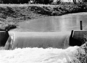
Figure 7-2 -- Cipoletti weir operating with full contractions at the
end
and on the crest.
|
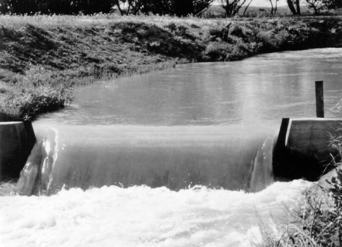
When sides of the flow channel act as the ends of a
rectangular weir,
no side contraction exists, and the nappe does not contract from the
width
of the channel. This type of weir is a suppressed weir and is
shown
on figures 7-1 and 7-3. To reproduce the full vertical rating,
contraction
of the suppressed weir that existed during its calibration requires
full
air ventilation under the nappe and the proper crest elevation.
|
Figure 7-3 -- Suppressed rectangular weir at a canal drop.
|
Velocity of approach is equal to the
discharge divided by the
flow section area at the head measuring station. Velocity of approach
is
important because it can change weir calibrations by effectively
reducing
the crest length and/or measuring head. In addition, a variable
discharge
coefficient results as increasing velocity changes the curvature of
flow
springing from the weir plates.
Free flow occurs when a thin-plate weir
allows free access of
air under the falling jet sheet or nappe. With free flow, head
measurements
at one upstream location determine discharge with knowledge of weir
size
and shape.
Downstream water rising above the weir crest
elevation produces a submerged
weir condition. When the downstream water surface is near or above
the crest elevation of a sharp-crested weir, accuracy of measurement
should
not be expected. "Submerged flow correction methods" or "submerged
calibrations" only produce estimates of discharge. The use of a
submerged
weir as a water measurement device is not good practice and should only
be done as a temporary, emergency procedure. Because of the large loss
of accuracy, designing thin-plate weirs for submergence should be
deliberately
avoided. However, submergence may happen unexpectedly or may be
temporarily
necessary. In such cases, flow can be estimated using special
techniques
discussed in Skogerboe et al. (1967), but not on a long-term basis.
A weir discharge measurement consists of
measuring depth or head
relative to the crest at the proper upstream location in the weir pool,
and then using a table or equation for the specific kind and size of
weir
to determine discharge. Commonly, a staff gage, described in
chapter
6, having a graduated scale with the zero placed at the same elevation
as the weir crest, measures head. Putting staff gages in stilling wells
dampens wave disturbances when reading head. Using vernier hook point
gages
in stilling wells produces much greater accuracy than staff gages.
These
staff gages must be zero referenced to the weir crest elevation.
Section
7 in chapter 8 provides more information regarding measuring head and
related
errors.