|
|
CHAPTER 6 - MEASURING AND RECORDING WATER STAGE OR HEAD
Water-stage recorders consist of a group of instruments that produce a record of water surface elevation with respect to time. The output can be analog (providing a graphical result) or digital (punched paper tape or stored or transmitted values). Important advantages of recorders over nonrecording staff gages are:
(1) In streams having daily fluctuations, continuous records provide the most accurate means of determining the daily average gage height.
(2) Maximum and minimum stage are recorded, and the time they occurred can be noted.
(3) Records can be obtained at stations where observers are not always available.
(a) Analog-Graphical Recorders
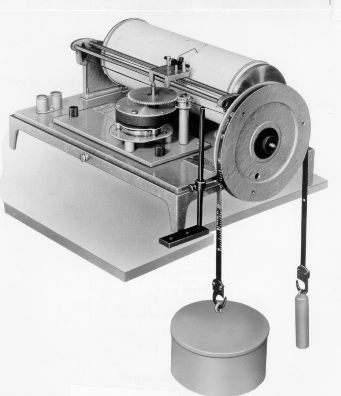
In general, analog or graphical recorders consist of two main elements: a clock mechanism actuated by a spring, weight, or electric motor and a gage height element actuated by a float, cable or tape, and counterweight. Four basic types of recorders use these elements. Figure 6-3 shows a horizontal drum recorder, in which the clock positions the pen along the drum axis, and the gage height element rotates the drum. This recorder is also available with a vertical drum. Another type of recorder also has a vertical drum, but the time and height elements have been reversed so that the clock mechanism rotates the drum.
|
|
These types of recorders usually operate using 8-day, spring-driven clocks. Electrical drives could also be used if a reliable source were readily available. The stylus, usually either a capillary pen or a pencil of proper hardness, must be capable of operation for the full 8 days without attention. To accommodate various water-stage differentials, ratios of water-stage change to recorder-chart change are available from 1:1 to 10:1 and should be specified at the time the recorder is ordered. The standard width of recorder paper is 10 inches (in), and all recorders come equipped with metal covers.
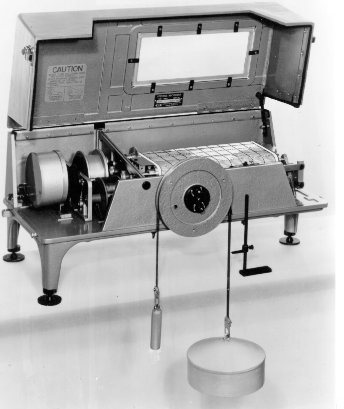
The fourth type of graphic recorder is shown on figures 6-4 and 6-5. The time element, consisting of a compensated, balanced, weight-driven clock, drives two parallel rolls, one of which holds the supply paper. The paper unrolls from the supply roll at a uniform rate and with constant tension and is taken up on the receiving roll. Speed of travel may be adjusted from 0.3 to 9.6 in per day on any standard instrument, and other chart speeds are available on special order. The normal chart length is 75 feet (ft).
|
|
|
|
The float activates a pen stylus which moves parallel to the axis of the rolls so that 1 in of travel represents a change in water stage of 1 ft. The stylus is designed so that it can be accurately set for gage height. The ratio of water surface change to stylus travel can also be adjusted to accommodate small to large ranges of depth. The range of the recorder is limited only by the length of the float cable because the stylus reverses direction at the point of maximum deflection. Capacity of the ink reservoir is sufficient for the recorder to operate for 60 days or longer.
(b) Digital Recorders
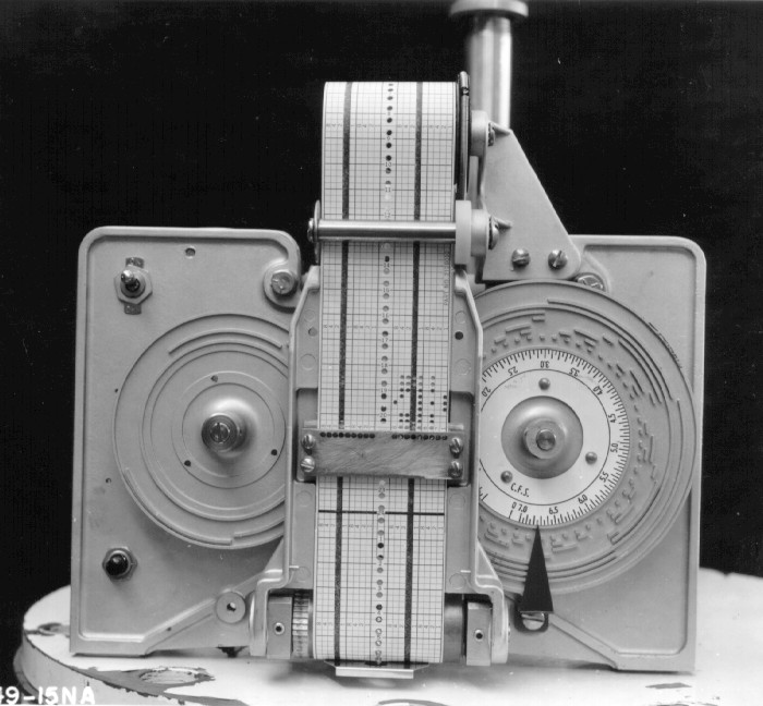
Digital recorders used in water stage measurements usually include two types: punched-paper tape (figure 6-6) and analog-to-digital data loggers. Both types are electrically operated (usually by batteries) and record numbers either on the paper tape or in memory at selected time intervals.
|
|
Water stage is transmitted to the punched-paper tape recorder, usually through shaft rotation on a float and pulley arrangement. Shaft rotation is converted by the recorder into coded punch-tape records (figure 6-7). The code consists of four groups of four punches each. In each group, the first punch represents "1"; the second, "2"; the third, "4"; and the fourth, "8." Thus, a combination of 1, 2, or 3 appropriate punches in a given group represents digits from 1 to 9. A blank (no punch) represents zero. Together, the four groups of punches represent all numbers from 0 to 9999.
|
|
Coding is done by either one or two identical disks that have raised ridges on the faces. Figure 6-6 shows a digital recorder with only one disk, which produces 2-digit numbers ranging from 0 to 99. Two disks would be used if 3- or 4-digit numbers are required. The right-hand disk is connected directly to the input shaft, and the left-hand disk is driven from the first disk by a 100-to-1 worm-gear reducer. One-hundred revolutions of the input shaft and the first disk cause one revolution of the second disk. A paper tape is moved upward through the punch assembly in the center of the instrument. The punch block contains a row of 18 pins or punchesC16 for information and 2 for feeding the tape. At the selected intervals of time, the punch assembly is pivoted on a shaft at the bottom, so the punch, paper, and pins are moved toward the disks. Those pins that strike raised ridges on the disks are forced through the paper, punching neat round holes. The pins that do not strike ridges do not punch holes. This record reflects the position of the disks, which is proportional to the water stage, all as a function of time.
The mechanically punched tape is still widely used at this time (1996) and is considered very practical for field use where temperature, moisture, and power conditions are widely variable. Electronic translators can convert punched tape records into suitable input for digital computers.
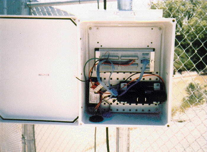
The most recent advances have been in the area of data loggers. This group of electronic instruments has evolved quickly over the last 10 years. Small, battery-operated, fully programmable units offer many features in addition to data recording (figure 6-8). Some type of transducer is required to sense the water stage with this type of recorder. Options range from a pressure transducer sensing water level in a stilling well to a pressure transducer on a bubbler system, to an angular transducer sensing shaft rotation on a float-driven system. In all cases, an analog (voltage or current) output is sensed, digitally recorded, and stored by the data logger. This type of system is perhaps best suited to the transmission of data via satellite or microwave, providing a central control location with current water stage information. Remote sites are very well suited to being powered by batteries which are charged through small solar cells. However, vandalism of the solar panels can be a problem because they must be exposed. Concealing solar panels in some way (such as in the top of a tree) can help.
|
|